نوفمبر 2019 ~ Communication World © كيفية جعل شكل التدوينات مربعة في البلوجر المصدر: https://www.mo3awin.com/2019/03/grid-layout-for-blogger.html

(Communication World (Ericsson / Huawei / Siae / Transmission Courses and Jobs

الأربعاء، 27 نوفمبر 2019

Telecom full imporntant Programs and basic packages

1-The below program used in Ericsson IPRAN Project to transfer script from Labtop to TCU using Winfiol program 

http://www.mediafire.com/file/sstjs304v4o14hn/Free_Sftp.rar/file


2-The below program used in Ericsson IPRAN Project , it's called WINFIOL

http://www.mediafire.com/file/sstjs304v4o14hn/Free_Sftp.rar/file 


3-The below program used in Ericsson 3G rollout Project to transfer C&D from Labtop to DUW

http://www.mediafire.com/file/qz5yzx00qx4jazc/WS_FTP_PRO-7.0.0.1.rar/file 


4-The below program used to login on DUW(3G Cabinet) , it's called RBS Element Manager

http://www.mediafire.com/file/fzs6ik1h7kj4cvi/RBS_JAVA.rar/file


5-The below program used to login on DUW(3G Cabinet) , it's called Moshell but it's advanced than RBS Element Manager but supposed to install Cygwin First

http://www.mediafire.com/file/220m1wra74j38le/moshell17.0d.zip/file  


6-The below program used to login on DUW(3G Cabinet) , it's called Cygwin but it's advanced than RBS Element Manager

 http://www.mediafire.com/file/y9ae28v879tgic7/cygwinBin4Emcli.zip/file


7-The below program used to formatting DUW and assigning IP address

http://www.mediafire.com/file/is8gm7in5incw5n/HyperTerminal.rar/file 


8-The below program used to login on PBC6200

http://www.mediafire.com/file/f10v9c53cas5zd0/PMS_SW_ver_2.12.rar/file


9-The below program used to login on DUG (2G Cabinet) , it's called OMT All released

  http://www.mediafire.com/file/vh461x2aanav1x1/OMT_55D.rar/file

http://www.mediafire.com/file/hgo1hlpeqctdp43/omt_52.rar/file 

http://www.mediafire.com/file/vh461x2aanav1x1/OMT_55D.rar/file

http://www.mediafire.com/file/kqoo37tu824wzsf/OMT_65.rar/file

http://www.mediafire.com/file/kqoo37tu824wzsf/OMT_65.rar/file 

http://www.mediafire.com/file/kqoo37tu824wzsf/OMT_65.rar/file 


10-The below Basic Package of DUG it's called G17

http://www.mediafire.com/file/5e7h2vf0ut7rsy9/GSM_BTS_RUS_SW_G17_11_R91A_%2528OMT_FORMAT%2529.zip/file


11-The below program used to login on Traffic Node (MLC version 17B)

http://www.mediafire.com/file/12w0gij2sei14ot/MINILINK_CRAFT_17B.rar/file


12-The below program used to login on Traffic Node (MLC version 14B) old version than previous one
 

http://www.mediafire.com/file/e7wdgez7gn47170/Mini_link_craft_14B.rar/file


13-The below program used to login on Ericsson Base band BB , It's Called Element Manager Luncher

 http://www.mediafire.com/file/b1i40n1rjrnf99w/EM_launcher.rar/file


14- The below program to capture print screen 

 http://www.mediafire.com/file/dmpeqwkdthnnz8s/purrint_14.rar/file


Share:

الأحد، 24 نوفمبر 2019

The difference between FDD and TDD in Microwave Transmission

The difference between FDD and TDD in Microwave Transmission


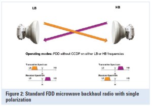
Microwave ODU with Antenna using FDD (Frequency Division Duplex)

Microwave links typically use Frequency-division duplexing (FDD) which is a method for establishing a full-duplex communications link that uses two different radio frequencies for transmitter and receiver operation. The transmit direction and receive direction frequencies are separated by a defined frequency offset.

Advantages of FDD

In the microwave realm, the primary advantages of this approach are:

  • The full data capacity is always available in each direction because the send and receive functions are separated;

  • It offers very low latency since transmit and receive functions operate simultaneously and continuously;

  • It can be used in licensed and license-exempt bands;

  • Most licensed bands worldwide are based on FDD; and

  • Due to regulatory restrictions, FDD radios used in licensed bands are coordinated and protected from interference, though not immune to it.


Microwave FDD (Frequency Division Duplexing)

Disadvantages to FDD

The primary disadvantages of the FDD approach to microwave communication are:

  • Complex to install. Any given path requires the availability of a pair of frequencies; if either frequency in the pair is unavailable, then it may not be possible to deploy the system in that band;

  • Radios require pre-configured channel pairs, making sparing complex;

  • Any traffic allocation other than a 50:50 split between transmit and receive yields inefficient use of one of the two paired frequencies, lowering spectral efficiency; and

  • Collocation of multiple radios is difficult.

  •  

TDD compared with FDD

Time-division duplexing (TDD) is a method for emulating full-duplex communication over a half-duplex communication link. The transmitter and receiver both use the same frequency but transmit and receive traffic is switched in time. The primary advantages of this approach as it applies to microwave communication are:

  • It is more spectrum friendly, allowing the use of only a single frequency for operation and dramatically increasing spectrum utilization, especially in license-exempt or narrow-bandwidth frequency bands ;

  • It allows for the variable allocation of throughput between the transmit and receive directions, making it well suited to applications with asymmetric traffic requirements, such as video surveillance, broadcast and Internet browsing;

  • Radios can be tuned for operation anywhere in a band and can be used at either end of the link. As a consequence, only a single spare is required to serve both ends of a link.


Disadvantages of TDD

The primary disadvantages of traditional TDD approaches to microwave communications are:

  • The switch from transmit to receive incurs a delay that causes traditional TDD systems to have greater inherent latency than FDD systems;

  • Traditional TDD approaches yield poor TDM performance due to latency;

  • For symmetric traffic (50:50), TDD is less spectrally efficient than FDD, due to the switching time between transmit and receive; and

  • Multiple co-located radios may interfere with one another unless they are synchronized.


Share:

الأحد، 17 نوفمبر 2019

why we assign IP : 192.168.x.x in LAN Networks.

IPV4 shortage problem :-

ودى المشكله الكبيره اللى واجهت منظمه ال IANA حيث انهم وجدوا ان ال IPs هتخلص بمرور الوقت فبداءوا يدوروا على حلول والمصيبه قبل ظهور الحلول فالتالى 

لو انا كشركه عندى 6 اجهزه وروحت اخد IP من ال IANA فهى هتشوف عدد الاجهزه عندهم كام وتقرر هتديك IP من انهى Class ف 6 اقل من 256 اذن هو Class C فهيدوك IP لشبكه تقدر تشيل 256 جهاز 

فبكده هيبقا عندى 6 مستخدمين و250IP مش مستخدمين ومتقدرش تديهم لحد غيرك

وكذلك لو محتاج 536IP فال IANA هتقرر ان Class B مناسب فهيتم ضياع 65000IP فما الحل :

Solution :-

1- used IPV5 (64 bits) ------ but used for researches only

2-used IPV6 (128bits) ------2^128 IPs = 3.4 * 10^38 IPV6 = 5 * 10^28 IPV6 / Human (will take it in session 21)

3-Private IPs + NAT (Network Address Translation)

وال IANA بتخصص IPs معينه فى كل Class وبتخليها Private بمعنى ان اى حد يستخدمها داخل ال LAN بتاعته من غير ماشتريها منهم وعندما يريد يطلع على ال WAN هنديله Public IP وده ال ISP بتدهونى عندما اشترك معهم وبدفع تمنه

وقبل الحل ده كانت ال IANA مصممه على ان اى حد واصل عل  LAN او WAN لازم يشترى منها Real IP (Public IP) لكن باستخدام ال Private IPs يقدر اكثر من جهاز ياخدوا نفس ال IP ويستخدموه داخل ال LAN بتاعتهم وعندما يشتركوا مع ال ISP ليطلعوا على ال Public WAN فال ISP هيرسل لهم Public IP والبروتوكول الذى Assign ال Real IP للمستخدميين هو ال PPPOE

وداخل ال Router يوجد به ال S/W NAT بحيث عندما يستقبل ال Router data ويجد Source IP هو Private IP وال data دى هتخرج على Public WAN فهيقوم بتشغيل ال NAT ليحول ال Private Source IP الى Public source IP 


اذن ال NAT هو S/W يحول ال Private IP الى Public IP


اخر جزء وهو ان ال NAT شغال One to One وده عيبه لان لو عندى 10 اجهزه فال LAN وعاوزين يطلعوا على ال Public WAN فهيحتاجوا 10Real IP وده هيعمل Waste to IPs فظهر بديله وهو ال PAT وده S/W يقدر يطلع 65000 جهاز على Real IP واحد 


Share:

الأحد، 10 نوفمبر 2019

CCAN Full Arabic Course : Session 7 Layer 3 Internet Layer ( IPV4 Header )

before we start let's take 2 examples on Subnetting first

Example 1 : For the given Major network : 199.20.30.0/24

we want to divide it using subnet mask 255.255.255,128

find : 1-Subnet mask in slash form

          2-number of subnets

          3-number of IPs/Subnet

          4-Number of hosts/subnet


solution : 199.20.30.0 is class C IP address (Network part is 24 bits , Host part is 8 bits )

and mask 255.255.255.128 is 11111111.11111111.11111111.10000000  mean /25

mean we borrow 1 bit from Host part 

SN=1 ....Number of subnets = 2^SN = 2^1 = 2

H=7 ......Number of IPs = 2^H = 2^7 = 128

Number of Hosts = 2^H-2 = 128-2 = 126


Example 2 : For the given Major network : 173.15.0.0/16

we want to divide it using subnet mask 255.255.252.0

find : 1-Subnet mask in slash form

          2-number of subnets

          3-number of IPs/Subnet

          4-Number of hosts/subnet


solution : 173.15.0.0 is class B IP address (Network part is 16 bits , Host part is 16 bits )

and mask 255.255.252.0 is 11111111.11111111.11111100.00000000  mean /22

mean we borrow 6 bit from Host part 

SN=6 ....Number of subnets = 2^SN = 2^6 =64

H=10 ......Number of IPs = 2^H = 2^0 = 1024

Number of Hosts = 2^H-2 = 1024-2 = 1022


Note : there is old subnetting standard use in some countries and old operating system 

   the standard is : While subnetting don't use first and last subnet and leave them for future use 

بمعنى انه يتم ترك اول واخر subnet لل future use اى لو بعمل subnetting اركز انى مخليش عدد ال Subnets=2 لانى مش هعرف استخدمهم وبالتالى 25/ لو كانت Class C لا يمكن استخدامها فى هذا ال Standard 


Internet Layer Protocol :-

IPV4 Header 

هنعرف شكل ال Header اللى بيتم اضافته على ال Segment لتتحول فالنهايه الى Packet 

ال data القادمه من Layer 4 تسمى Segment 

ال data القادمه من Layer 3 تسمى Packet

ال data القادمه من Layer 2 تسمى Frame


Share:

الجمعة، 8 نوفمبر 2019

LAG (Link Aggregation Group) & LACP (Link Aggregation Control Protocol)

LAG (Link Aggregation Group) & LACP (Link Aggregation Control Protocol)

Link Aggregation Groups (LAG) and Link Aggregation Control Protocol (LACP) are methods to provide more than one link between two switches and automate its configuration and maintenance, respectively. Let us look at why LAG/LACP are required and their advantages, in this article.


LAG – Link Aggregation Groups


To connect two switches, we use a cable to connect two physical ports (one in each of the switches) and configure them as a trunk. But a single trunk has bandwidth limitations. We can use stacking to obtain higher bandwidth, but stacking is mostly proprietary and supports a limited distance. In order to obtain high-bandwidth trunk lines between two switches (or two devices), we can use LAG – Link Aggregation Group.

LAG is a process of inter-connecting two switches with two or more links between them (or between a switch and a server), so that multiple links are combined into one bigger virtual link that can carry a higher (combined) bandwidth. All these multiple links participating in a Link Aggregation Group act like a single large (virtual) link.

If two switches support 1 GE ports, multiple ports from one switch can be connected to multiple ports in another switch to provide high-bandwidth connections (2 GE, 3 GE, etc) between the switches.

A practical situation to consider: If two switches are connected to each other with a bandwidth of 1 GE and the network administrator feels that it is insufficient, they can either buy another switch with 10 GE trunk support (hardware upgrade, more expensive) or just connect multiple ports between these two switches and configure them as a Link Aggregation Group. This approach is not only inexpensive (doesn’t require hardware upgrades), but also allows a granular upgrade of interconnect bandwidth between the two switches.

LAG is also used for increasing link reliability. Since multiple links connect two devices, even if one fails the other links keep carrying the information and the traffic on the failed link is also transferred to them. That way, loss of a single link between two switches doesn’t stop the communication between them. Multiple links participating in a LAG can also load-balance the traffic between them so that traffic is evenly distributed.

The number of links that can combine to form a larger link between two devices is generally restricted by the hardware vendor. LAG is a static protocol and needs to be configured individually for each pair of physical ports. LAG is a standard.


LACP – Link Aggregation Control Protocol

LACP is similar to LAG, where multiple ports/links between two switches combine to provide higher bandwidth links between them. Additionally, ports that are LACP enabled can automatically configure themselves into trunk groups, without any manual configuration/intervention.

The main purpose of LACP is to automatically add/delete individual links to the aggregate bundle, while adding new links and also after recovering from link failures. LACP can monitor to verify if all the links are connected to the right group. Basically, LACP helps automate the configuration and maintenance of LAG’s.

LACP is a dynamic protocol. It is sufficient if multiple ports on various devices are LACP enabled, once. LACP is a standard and hence LACP can be implemented between multi-vendor switches. 

LACP should be enabled on the trunk ports initially in order for both the participating switches/devices that support the standard, to use it. If there are more links (between two devices) than what is supported by the vendor for LACP, the additional links are placed in stand-by mode and activated automatically when a link fails.

Share:

الخميس، 7 نوفمبر 2019

CCAN Full Arabic Course : Session 6 Layer 3 Internet Layer ( Subnetting )

عرفنا فال Session اللى فاتت المشكله الكبيره اللى واجهت IANA وهى ان ال IPs قربت تخلص بسبب ان معظمها يتم اهداره بدون فائده بسبب ان لو شركه محتاجه مثلا 1000IPs فال IANA بتشوف اى ال Classes مناسبه لعدد ال IPs فتجد ان Class B هو المناسب فتعطى لها range IP يقدر يشيل 65536IP فالشركه تستخدم منهم 1000 فقط وترمى الباقى 

فوجدوا بعض الحلول لتعويض هذا وهو 

استخدام ال IPV6

استخدام بروتوكول ال NAT وال PAT 

 والاهم  هو استخدام ال Subnetting


قبل البدء فال Subnetting تعالو ناخد مثالين عن ال IP addressing 

EX1 : we have  IP:177.7.7.7 for adevice

Find the class of this IP , Network Address , number of IPs in this network and number of Hosts


Solution :

177.7.7.7 is class B address

Network Address is :177.7.0.0          (All Host bits =0)

Direct Broadcast IP :177.7.255.255  (All Host bits =1)

No. of IPs = 2^H = 2^16 = 65536

No. of Hosts = 2^H-2 = 65536-2 = 65534


EX2 : we have  IP:205.60.70.80 for adevice

Find the class of this IP , Network Address , number of IPs in this network and number of Hosts


Solution :


205.60.70.80 is class C address

Network Address is :205.60.70.0

Direct Broadcast IP :205.60.70.255 

No. of IPs = 2^H = 2^8 = 256

No. of Hosts = 2^H-2 = 256-2 =254


Subnetting : -

  its Mean Sub networking اى تقسيم الشبكات


  • It's dividing Major Network in to smaller networks called subnets

  • This is done by borrowing part of host bits and give them to network part

 وهى تقسيم الشبكه الى عده شبكات بحيث لو شركه محتاجه عدد معين من ال IPs يتم اعطاءها هذا العدد بالظبط دون اعطاءها عدد زياده ويتم اهدار هذا العدد الزائد

كيف يتم ذلك : مبداءيا الشبكه لو هيتم تقسيمها فلازم يتم تقسيمها بالمضاعفات التاليه 

2 , 4 , 8 , 16 , 32 , 64 , 128 , 256 , 512 , 1024 وهكذا 

اى لو شركه محتاجه مثلا 60IP فبدلا من اعطاءها IP يشيل 256 من Class C هيتم اعطاءها Subnet من Class C يشيل 64IP ولكن لا استطيع اعطاءه 60IP بالظبط فبذلك هيتم اهدار 4IPs بدلا من اهدار 196IPs

نفترض ان عندى Class C IP :205.6.7.0 وعاوز اقسمها 4 اقسام كل قسم 64IP فكيف يتم ذلك

.

وبكده لو شركه عاوز 60IP هديلهم Subnet 1 ولو شركه عاوز 120IP هديهم 2Subnet او اجيب شبكه تانيه واقسمها 2Subnet كل Subnet =128IP وهكذا

اذن الشبكه قبل ماتتقسم تسمى Major Network لكن بعد مايتم تقسيمها فكل قسم يسمى Subnet

وال Major Network قبل ماتتقسم كان ليها Network address و Direct Broadcast address واحد اما الان بعد تقسيمها ل Subnets فكل Subnet تعتبر Network لوحدها ليها Network Address و Direct Broadcast ِخاص بها 


This is done by borrowing part of host bits and give them to network part

الجمله دى هى فكره ال Subnetting وهى انك بتستلف شويه bits من ال host part وتحطهم مع ال الجزء بتاع ال Network بحيث تكون عدد ال Subnets = 2^SN

SN=refer to number of borrowing bits from host part

EX: if we have this network IP :41.x.x.x

before borrowing : Host Part is 24 .. then number of IPs = 2^24

if we borrow 8 bits from host part

then number of host bits = 24-8 = 16bits

then number of subnet =2^8 = 256 subnets

number of hosts/subnet=2^16 =6553 hosts/subnet


if we borrow 2 bits only from Host part

then number of host bits = 24-2 = 22bits

then number of subnet =2^2 = 4 subnets

number of hosts/subnet=2^22 =4000000 hosts/subnet

ودى مطبقه فعلا حيث ان شبكه 41.0.0.0 متقسمه 4Subnets وهم كالتالى

41.0.0.0   for TEDATA

41.64.0.0 for Link

41.128.0.0 for TEDATA

41.192.0.0 free

وازاى بنعبر عن ال Subnets اى ازاى بنعرف اذا كانت الشبكه متقسه Subnets ولا هى Major network

عن طريق ال MASK او مايسمى ال Subnet Mask 

وال Mask عباره عن 32bits يتم وضعه مع ال IP بحيث انه يحدد اذا كانت ال network متقسمه ولا هى Major network 

وهو عباره عن 1and 0 وال 1 يمثل ال network part اما ال 0 يمثل ال Host Part 

يعن ايه 

نفترض انى عندى   private IP) IP:10.30.40.50 والشبكه دى مش متقسمه 

ال IP ده تبع Class A فال Mask بتاعه هيكون كالتالى

  11111111.00000000.00000000.00000000

       0       .       0       .      0        .    255

               8/

دى التلات طرق اللى بنكتب بيها ال Subnet Mask 

Hence the Ip will written as : 10.30.40.50 /8 ... mean no subnetting (Default Mask)

or IP : 10.30.40.50  , Subnet Mask : 255.0.0.0


ِAnother Example : IP:172.16.8.30 (Private IP)

Class B Address 

it's mean the first 2 octet for network Part and Last two octet for Host part 

then we have to represent network parts by 1 and host part by 0

Subnet Mask : 11111111.11111111.00000000.00000000

                                255  .     255     .       0       .       0

                                                      /16

And this is default mask foe Class B address ( No subnetting )


Another Example : IP:192.168.1.1 (Private IP)

Class C Address 

it's mean the first 3 octet for network Part and Last octet for Host part 

then we have to represent network parts by 1 and host part by 0

Subnet Mask : 11111111.11111111.11111111.00000000

                                255  .     255     .    255    .       0

                                                      /24

And this is default mask foe Class C address ( No subnetting )


Example : IP :205.6.7.x

and Mask :11111111.11111111.11111111.11000000

How many Subnet , IPs /Subnet , 205.6.7.200 in which subnet


Solution : 205.6.7.x (Class C) mean 8 bits for Host and 24 bits for Network

Mask :11111111.11111111.11111111.11000000 ( /26 ) (255.255.255.192)

it's mean we borrow 2 bits from Host part 

Hence SN=2 and H=6

hence number of subnets = 2^SN = 2^2 = 4

hence number of IP/Subnet = 2^H = 2^6 = 64

hence we have 4 subnets divided as following :

205.6.7.0 , 205.6.7.64 , 205.6.7.128 , 205.6.7.192

hence 205.6.7.200 belong to Subnet 4

/27 mean we borrow 3 bits from host part (255.255.255.224)

SN = 3 ...... No. of Subnets = 2^3 = 8

H = 5 ........No of IP/Subnet = 2^5 = 32

/30 mean we borrow 6 bits from host part (255.255.255.252)

SN = 6 ...... No. of Subnets = 2^6 =64

H = 2 ........No of IP/Subnet = 2^2 =4

وده ااقصى Subnetting اقدر اعمله لانه بيعطينى 4IPs فقط منهم اول IP اسمه ال Network address

واخر  IP هو ال Direct BroadCast Address وهيتبقى عندى 2IP فقط وده ال Subnet المستخدم فال Point to point network لانى عندى 2Devices فقط اى محتاج 2IP فقط


/31 mean we borrow 7 bits from host part (255.255.255.254)

SN = 7 ...... No. of Subnets = 2^7 =128

H = 1 ........No of IP/Subnet = 2^1 =2

وال 2IPs دول هيبقوا Network Address and Broadcast address اى انها شبكه فاضيه

وهذا ال Mask لا يوجد له استخدام فى عالم ال Network


وبكده يكون ال Subnetting خلص وعرفنا ايه الفايده بتاعته وهنبدأ ال Session القادمه فى Header االخاصه ب Layer 3 


ان شاء الله هنكمل ال Internet Layer  فى Session 7 وتقدر تشوفها على اللينك التالى

https://telecommunicationworldss.blogspot.com/2019/11/ccan-full-arabic-course-session-6-layer_10.html


Share:

الثلاثاء، 5 نوفمبر 2019

مطلوب مهندسين اتصالات للمصريه للاتصالات خبره وحديثى التخرج

مطلوب مهندسين خريجى اتصالات واليكترونيات للعمل لدى شركه المصريه للاتصالات 

خبره وحديثى التخرج

من سكان المناطق التاليه : الاسماعيليه , السويس , بورسعيد , سيناء

 على الميل CV يرجى ارسال ال

Ashraf. Khaliel@te.eg

amr.sedky@te.eg 

and mention in Subject : Communication Engneer

any mail will come without subject will be rejected 


Share:

الأحد، 3 نوفمبر 2019

CCAN Full Arabic Course : Session 5 Layer 3 Internet Layer ( IP Addressing )

Layer 3 :- Internet Layer - PDD (Packet Data Unit) :-

It's responsible for end to end data delivery

وظيفه هذه ال Layer هى نقل ال Packet from end to end

ودى اهم Layer فى شغل مهندس الشبكات لان Layer 1 خاصه بالتوصيلات ودى بيقوم بيها فنيين الشبكات 

وLayer 2 خاصه بال MAC Address , MAC Method , Flow Control , MAC Frame ودى بتيجى متبرمجه على كروت ال NIC اما Layer 3 فهى خاصه بال Logical Addressing , Routing ودى شغل مهندس الشبكات وهندرس فيها 7Sessions بدءا من هذا ال Session

Logical Addressing : It's S/W address (Given By Configuration)

عكس ال MAC Address هو H/W Address (Physical Address)

Used For End to End Reachability 

والمسؤله عن تنظيم هذه ال Logical Addressing (IPs) هى ال IANA 

Responsible for distribution of Logical address 

وممكن اخذ منها ال IP مباشره منها او اخذ من ال service Provider (TE-Data , Link,...)

 
ال IP Address يتكون من Network Part and Host Part 

وال Network Part هو الجزء اللى بتعطيه ال Service Provider للمستخدم اما ال Host Part فده اللى بتحكم فيه وبوزعه على الاجهزه عندى

 تانى حاجه هى ال Routing 


نفترض ان عندى فرعين لشركتى وعاوز اوصلهم مع بعض فلازم اوصل الاجهزه الموجوده فى كل فرع على Router واقوم بتوصيل الفرعين اى ال 2Router بمساعده ال Service Provider وهو سيقوم بتوصيل ال 2Routers بتوعى قى الفرعين على Router داخل السنترال او على Switch 
ال Router اللى فى الفرعين  بيتوصلوا بال Router اللى فى السنترال على كارت ال WIC وده ال Interface لل WAN Network اما ال Router بيتوصل مع ال Switch داخل ال LAN على كارت ال NIC 
WIC port is Serial 
NIC port is Ethernet 
يوجد ايضا Console port داخل ال Routerوده المستخدم فى ال Configuration حيث ان ال PC بيتوصل على هذا ال Port فى حاله ال Configuration وده ايضا Ethernet port 

نرجع للنقطه الاساسيه وهى ال Routing فلو ال Router اللى داخل السنترال جاتله Packet من احد الفروع ومش عارف ال Destination بتاعها فهيعمل ايه 

لو كان Switch كان بيعمل Flood ويستنى الرد من ال Destination وبعد كده يبنى ال MAc Table 

اما ال Router فلا يستطيع عمل ذلك لانه داخل WAN ال flood ممكن توقع ال Network كلها 

 Router will drop Packet if Destination IP is unknown 

اذن ال Router لازم يتعلم ويبنى ال Table بتاعه واسمه ال Routing Table 

وال Protocol اللى بيعلمه ال Routing هى بروتوكولات عديده واشهرهم ال OSPF 

فمثلا فالمثال اللى فوق ال Routing Table سيكون بالشكل التالى 

Network        :       Port

11.0                         S1

 12.3                         S0

ودى مقدمه سريعه عن هذه ال Layer ونبدا الشرح بالتفصيل


  1-Logical Addressing :-

واشهر بوتوكول مسئول عن ال Logical addressing هو ال IPV4

 وهندرس 2Session فيها بدءا من هذا ال Session 

IPV4 (Internet Protocol Version 4 ) :-

 وهو البروتوكول المستخدم فى Layer 3 (Internet Protocol ) المسئول عن ال  end to end data delivery

It's responsible for :

1-Logical Addressing (IPV4 Addressing ) :--- S/W Address given by Configuration  "End to End addressing "

2-Encapsulating data :-----End to End ( IP Header ) 

اى هو المسؤل عن وضع ال Header الخاص ب Layer 3


قبل مانتكلم عن ال IPV4 يلا نرجع ل Layer2 ونتكلم على نقطه وهى ال MAC Address

وعرفنا انه نوع من انواع ال Addressing يستخدم لنقل ال Frame from Hop to Hop

النقطه هنا ان ال MAC Address مش النوع الوحيد فى Layer 2 اللى بيعمل كده , فيه 3 انواع اخرى ومستخدمين ولكن مستخدمين فال WAN اما ال MAC يستخدم فال LAN 

لو انا داخل ال LAN فال Addressing اللى هيستخدم فى Layer 2 فى توصيل ال Frame from Hop to Hop هو ال MAC Address و اما لو انا فال WAN فال Addressing اللى هيستخدم فى LAyer2 فى توصيل ال Frame from hop to hop هو واحد من ثلاثه انواع وهم :

X.25 , DLCI , VPI/VCI

X.25 : مكون من 8Bits ويستخدم لو ال Communication Technology المستخدمه فال WAN هى ال X.25 technology


DLCI: مكون من 10Bits ويستخدم لو ال Communication Technology المستخدمه فال WAN هى ال Frame Relay FR

VPI/VCI : مكون من 16Bits ويستخدم لو ال Communication Technology المستخدمه فال WAN هى الATM or DSL 


MAC : مكون من 48Bits ويستخدم لو ال Communication Technology المستخدمه فال LAN هى ال Ethernet or WIFI

وقريبا ال Ethernet هو اللى هيشتغل فال WAN كما هو شغال فال LAN 

اى قريبا ال MAC هيشتغل فال WAN كما هو شغال فال LAN 

اذن الخلاصه From hop to hop يوجد العديد من ال addressing اما From End to End يوجد فقط نوع واحد وهو ال IPV4


  IPV4 Address :-

It's 32 bits address and represented in dotted decimal octet 

dotted اى بنضع دوت , decimal اى نمثله بارقام وليس binary كما هو بالمثال التالى , octet اى كل 8bits نضع دوت

Ex: 10101010.11111111.00000000.00001111  

Decimal : 170.255.0.15

وال IANA (Internet Assigned Number Authorith) هى المسئوله عن توزيع ال IPs 


IPV4 Classes :- 

1- Class A:-

 ودى الخاصه بالشركات الكبيره جدا على مستوى العالم اى عندها عملاء كتيره جدا مثل TEdata and orange وهذا ال Class يبدأ اول Octet من 1--------126


مثال على هذا النوع وهو TEdata واخده Network ID :41 فبكده كل ال IPs بتاعت ال Hosts هتبدأ ب 41.0.0.0 الى 41.255.255.255
اذن كام احتمال عندى او بمعنى اصح كم عدد ال Hosts فى هذه ال Network 


Number of  IPs  = 2^H

حيث ان ال H تمثل عدد ال Host bits وهنا فى Class A عدد ال Host bits = 24

Hence Number of IPs = 2^24 = 16777216 IPs

وفى عالم ال network اول IP واخر IP لا يتم اعطائهم لل Hosts لان اول IP يمثل ال Network Address واخر IP يمثل ال Direct Broadcast Address


Hence Number of  Hosts  = 2^H-2


2- Class B:- 

 ودى الخاصه بالشركات متوسطه الحجم  عندها عملاء بالالاف  وهذا ال Class يبدأ اول Octet من 128----------191 وثانى Octet هيبقى عادى من 0------255


Number of IPs = 2^H = 2^16 = 65536 IPs

Hence Number of  Hosts  = 65536 -2 =65534 Hosts


3- Class C:-

 ودى الخاصه بالشركات متوسطه الحجم الصغيره عندها عملاء قليله وهذا ال Class يبدأ اول Octet من 192----------223 وثانى Octet وثالث Octet هيبقى عادى من  0------255

 Number of IPs = 2^H = 2^8 = 256 IPs

Hence Number of  Hosts  = 256 -2 =254 Hosts


4- Class D:- 

هذا ال Class يبدأ اول Octet من 224----------239


used For MultiCast
وسعر ال IP فيه اغلى من سعر ال IP بتاع اول تلات Classes ب 10 اضعاف وذلك لان استخدامات هذا ال Class تجاريه , لانه يستخدم فال Games اى لو دخلت على موقع FIFA وهتلعب لعبه اونلاين مع عدد من الناس فتقوم FIFA بارسال MultiCast IP لكل الناس المشاركه فاللعبه وهذا ال IP مؤقت يأخده الجهاز المشاركه فاللعبه مؤقت
Address for Application

ده ال Class ملوش علاقه بال Network ID و Host ID ولكن ال IANA محدده مجموعه IP خاصه بال Class D وهم 256000000IP for MultiCast

لو ال Multicast IP مش موجود وعاوز العب لعبه مع 3 اشخاص اونلاين فما البديل 
عندما ارسل شىء ليهم هما ال 3 فلازم ارسل نسخه بال Unicast IP بتاع اول جهاز ثم نفس النسخه بال Unicast IP لثانى جهاز ثم ثم حتى ارسل لكل الاجهزه المشاركه فنفس اللعبه 

5- Class E:-

هذا ال Class يبدأ اول Octet من 254----------240

Used for researches and Military Applications.


Reserved IPs :-

0.x.x.x ---------Reserved only 0.0.0.0 and remaining 16000000 not used

127.x.x.x------Reserced only 127.0.0.1  and remaining 16000000 not used

255.x.x.x------Reserced only 255.255.255.255  and remaining 16000000 not used

اى تم استخدام IP واحد فقط فى كل شبكه من الشبكات السابقه وباقى ال IPs فى كل شبكه لم تستخدم


0.0.0.0 :-

يعبر عن عنوان جميع الشبكات الموجوده فالعالم 

بمعنى على مستوى العالم يوجد حوالى 300000 شبكه فلازم كل Router يبقا مسجل كل هذه الشبكات فال RAM عنده فال Routing table بتاعه علشان لما جهاز يبعت ليه data ويقرا ال Destination IP بتاعها يعرف هيوديها فين لان ال Router لو مش عارف هيبعت لمين مش بيعمل Flood لل Data زى ال switch ولكن بيعملها drop وده معناه ان كل router لازم يشيل 300000 شبكه فال database بتاعته فهيبقى غالى جدا , ال router بتاع الشركات وال service provider عنده الامكانيه دى لانه غالى بس معنى كده انى محتاج router بملايين الجنيهات للبيوت ايضا علشان يقدر يخزن البيناتات دى ويجى هنا دور هذا ال IP  0.0.0.0. وبكده ال Router مش محتاج يسجل كل الشبكات الموجوده فالعالم عنده ولكن يضع فقط هذا ال IP 0.0.0.0 فال Routing table ويحطها ادام ال serial Port WIC الواصل على ال Service provider وبذلك ال Router هيسجل فال Routing tableسطرين فقط وهم شبكه ال LAN اللى هو موجود فيها ويحطه على port E0 مثلا الموجود على ال NIC  وتانى سطر هو 0.0.0.0 ويحطه على port S0 مثلا الموجود على ال WIC

وبكده لو جاى data لل Router ولقى ال Destination IP بتاعها خاص بال LAN network فهيطلع ال data على port E0 ولقى لقى غير كده هيطلع ال data على Port S0 اى سكه اللى ملوش سكه ولما توصل لل service provider هيعرف هى رايحه فين لانه مسجل ال 300000 شبكه عنده

127.0.0.1 :-

Used for Loop back test  (Internal S/W test )

وده اشهر IP مستخدم فال Troubleshooting لان بي Check على ال TCP/IP الموجوده فال PC لان عندما يتم ت Setup windows على الجهاز بينزل معاه ال TCP/IP فلو عملت Ping 127.0.0.1 فهو بي Check عليه فلازم يجيلى reply علشان اتأكد ان ال S/W عنده تمام فلو مجاليش Reply معناه جهازى فيه مشكله ممكن بسبب فيروس او ال S/W متصطبش بالكامل او حدث مشكله عند تنزيل ال windows 

فدى خطوه بت Check بيها على TCP/IP قبل ان اخذ قرار ان الشبكه فيها مشكله


255.255.255.255 :-

Called All hosts broadcast Address (General IP ) ( Local Broadcast )

اى لو حطيت ال IP ده فال Destination فكل الاجزه فالعالم هتستقبله وتعمل لل data processing

شبه ال Broadcast MAC :FFFFFFFFFFFF

اذن يوجد نوعين لل Broadcast الخاص بال IP

Direct Broadcast : وهو ال Broadcast الذى يرسل باسم Network معينه مثل 126.255.255.255

فده لو اتبعت فكل الاجهزه اللى فى شبكه 126.0.0.0 هتستقبلها وتعمل لها Processing 


Local Broadcast : هيت ارسال ال data لكل الاجهزه فالعالم والكل هيعمل لها processing


IPV4 shortage problem :-

ودى المشكله الكبيره اللى واجهت منظمه ال IANA حيث انهم وجدوا ان ال IPs هتخلص بمرور الوقت فبداءوا يدوروا على حلول والمصيبه قبل ظهور الحلول فالتالى 

لو انا كشركه عندى 6 اجهزه وروحت اخد IP من ال IANA فهى هتشوف عدد الاجهزه عندكم كام وتقرر هتديك IP من انهى Class ف 6 اقل من 256 اذن هو Class C فهيدوك IP لشبكه تقدر تشيل 256 جهاز 

فبكده هيبقا عندى 6 مستخدمين و250IP مش مستخدمين ومتقدرش تديهم لحد غيرك

وكذلك لو محتاج 536IP فال IANA هتقرر ان Class B مناسب فهيتم ضياع 65000IP فما الحل :

Solution :-

1- used IPV5 (64 bits) ------ but used for researches only

2-used IPV6 (128bits) ------2^128 IPs = 3.4 * 10^38 IPV6 = 5 * 10^28 IPV6 / Human (will take it in session 21)

3-Private IPs + NAT (Network Address Translation)

وال IANA بتخصص IPs معينه فى كل Class وبتخليها Private بمعنى ان اى حد يستخدمها داخل ال LAN بتاعته من غير ماشتريها منهم وعندما يريد يطلع على ال WAN هنديله Public IP وده ال ISP بتدهونى عندما اشترك معهم وبدفع تمنه


وقبل الحل ده كانت ال IANA مصممه على ان اى حد واصل عل  LAN او WAN لازم يشترى منها Real IP (Public IP) لكن باستخدام ال Private IPs يقدر اكثر من جهاز ياخدوا نفس ال IP ويستخدموه داخل ال LAN بتاعتهم وعندما يشتركوا مع ال ISP ليطلعوا على ال Public WAN فال ISP هيرسل لهم Public IP والبروتوكول الذى Assign ال Real IP للمستخدميين هو ال PPPOE

وداخل ال Router يوجد به ال S/W NAT بحيث عندما يستقبل ال Router data ويجد Source IP هو Private IP وال data دى هتخرج على Public WAN فهيقوم بتشغيل ال NAT ليحول ال Private Source IP الى Public source IP 


اذن ال NAT هو S/W يحول ال Private IP الى Public IP


اخر جزء وهو ان ال NAT شغال One to One وده عيبه لان لو عندى 10 اجهزه فال LAN وعاوزين يطلعوا على ال Public WAN فهيحتاجوا 10Real IP وده هيعمل Waste to IPs فظهر بديله وهو ال PAT وده S/W يقدر يطلع 65000 جهاز على Real IP واحد 


معلومه عالماشى :

ما الفرق بين ال Private WAN and Public WAN 

ال Private WAN هى WAN خاصه بالشركه وفروعها مثل البنك الاهلى رابط فروعه مع بعض باستخدام ال Private WAN اى كل فرع الاجهزه داخله لها Private IPs ومروبطين مع بعض باستخدام ال ISP والتيم المسئول عنهم فال ISP يسمى ال Enterprise team

اما ال Public WAN ودى شبكه ال WAN العاديه


127.0.0.0 تبع انهى Class

هذا ال IP هو Classless IP


ان شاء الله هنكمل ال Internet Layer  فى Session 6 وتقدر تشوفها على اللينك التالى

https://telecommunicationworldss.blogspot.com/2019/11/ccan-full-arabic-course-session-6-layer.html

Share:
Hosam Hassan. يتم التشغيل بواسطة Blogger.