فبراير 2019 ~ Communication World © كيفية جعل شكل التدوينات مربعة في البلوجر المصدر: https://www.mo3awin.com/2019/03/grid-layout-for-blogger.html

(Communication World (Ericsson / Huawei / Siae / Transmission Courses and Jobs

السبت، 23 فبراير 2019

مطلوب مهندسين اتصالات بالمصرية للاتصالات


المجال:                  هندسة
الراتب:                  بعد المقابلة 
مكان الوظيفة:         cairo, مصر
التعليم:                  بكالوريوس هندسة
الخبرات:               FreshYear
موعد الانتهاء::       17-06-2019
تاريخ الاضافة::      17-02-2019
 
 
وصف الوظيفة:

مهندسين اتصالات سنهم ميزيدش عن ٣٠ سنة وتقديرهم ميقلش عن جيد في محافظات (القاهرة - قنا - السويس - الإسماعيلية ) ييعتوا ال CVs بتاعتهم على الميل ده Inas.mehaseb@te.eg


Share:

الجمعة، 22 فبراير 2019

Link budget definition and calculation (Important point in Transmission)

Link budget

A link budget is an accounting of all of the gains and losses from the transmitter, through the medium (free space, cable, waveguide, fiber, etc.) to the receiver . 
It accounts for the attenuation of the transmitted signal due to propagation, as well as the antenna gains  and other losses. Randomly varying channel gains such as fading are taken into account by adding some margin depending on the anticipated severity of its effects. The amount of margin required can be reduced by the use of mitigating techniques such as antenna diversity or frequency hopping.
A simple link budget equation looks like this:
Received Power (dB) = Transmitted Power (dB) + Gains (dB) − Losses (dB)


A link budget equation including all these effects, expressed logarithmically, might look like this:
where:
= received power (dBm)
= transmitter output power (dBm)
= transmitter antenna gain (dBi)
= transmitter losses (coax, connectors...) (dB)
= path loss, usually free space loss (dB)
= miscellaneous losses (fading margin, body loss, polarization mismatch, other losses...) (dB)
= receiver antenna gain (dBi)
= receiver losses (coax, connectors...) (dB)
The loss due to propagation between the transmitting and receiving antennas, often called the path loss, can be written in dimensionless form by normalizing the distance to the wavelength:
(where distance and wavelength are in the same units)
When substituted into the link budget equation above, the result is the logarithmic form of the Friis transmission equation.
In some cases, it is convenient to consider the loss due to distance and wavelength separately, but in that case, it is important to keep track of which units are being used, as each choice involves a differing constant offset. Some examples are provided below.
(dB) = 32.45 dB + 20×log[frequency(MHz)] + 20×log[distance(km)] [1]
(dB) = - 27.55 dB + 20×log[frequency(MHz)] + 20×log[distance(m)]
(dB) = 36.6 dB + 20×log[frequency(MHz)] + 20×log[distance(miles)]
These alternative forms can be derived by substituting wavelength with the ratio of propagation velocity (c, approximately 3×10^8 m/s) divided by frequency, and by inserting the proper conversion factors between km or miles and meters, and between MHz and (1/sec).


  receiver sensitivity ودي اقل باور يستقبلها ال receiver علشان يقدر يرجع ال Signal لل baseband form تاني باقل bit error rate
..................
  free space loss وده الفقد الناتج عن أن الاشاره مشيت مسافه معينه ودي تعتبر بتتغير علي حسب حاجتين مهمين وهم distance , frequency
FSL = 36.6 + 10 log frequency + 10 log distance
.................
  antenna Gain وخد بالك ان الانتينا تعتبر passive Element يعني المفروض مش بتدي Gain ولكن لما نقول أن ال dish Antenna ليه Gain حوالي 18 dbi ده معناه أن عندها القدره علي توجيه الباور اللي داخلها كله في اتجاه معين اكبر من قدره ال istropic antenna بقيمه 18 . اذن ال Gain بيتترجم الي directivity
.......................
  feeder loss وده الفقد اللي بيضيفه الكابل اللي شايل اشاره الميكرويف من الكابينه تحت لحد ال dish فوق . وال loss ده بيتقاس بال DB و بيكون علي حسب نوع ال feeder وال cross section بتاعه وال distance طبعا
يعني مثلا 1 Db لكل 100 meter . ده مثال
....................
  gas attenuation ودي بتتضاف في المعادله بي بال negative لانها loss وليست Gain ودي بتعبر عن قيمه امتصاص ال gases الموجوده في ال atmosphere لل Signal ودي بتتغير بتغير ال frequency
يعني مثلا بنحاول نتجنب دايما ال 24 - 25 GHz لان فيه Gas attenuation عالي
.....................
  rain attenuation ودي مهم جدا خصوصا في ال coastal area وطبعا ال width بتاعه ال rain drop بتفرق وكمان نوع ال polarization اللي بتبعت بيه هيفرق جدا . علشان كده لو في area فيها rain rate عالي بنستخدم معاها vertical علشان ال rain ليحصلها spread في ال horizontal plane وبتكون effective اوي فيه
Share:

MSAN ( Multi-service access node )

A multi-service access node (MSAN), also known as a multi-service access gateway (MSAG), is a device typically installed in a telephone exchange (although sometimes in a roadside serving area interface cabinet) which connects customers' telephone lines to the core network, to provide telephone, ISDN, and broadband such as DSL all from a single platform.
Prior to the deployment of MSANs, telecom providers typically had a multitude of separate equipment including DSLAMs to provide the various types of services to customers. Integrating all services on a single node, which typically backhauls all data streams over IP or Asynchronous Transfer Mode can be more cost effective and may provide new services to customers quicker than previously possible.
A typical outdoor MSAN cabinet consists of narrowband (POTS), broadband (xDSL) services, batteries with rectifiers, optical transmission unit and copper distribution frame..

A multiservice access node is a broader term that refers to a group of commonly used aggregation devices. These devices include digital subscriber line access multiplexers (DSLAMs) used in xDSL networks, optical line termination (OLT) for PON/FTTx networks, and Ethernet switches for Active Ethernet connections. Modern MSANs often support all of these connections, as well as providing connections for additional circuits such as plain old telephone service (referred to as POTS) or Digital Signal 1 (DS1 or T1).
The defining function of a multiservice access node is to aggregate traffic from multiple subscribers. At the physical level, the MSAN also converts traffic from the last mile technology (for example, ADSL) to Ethernet for delivery to subscribers.
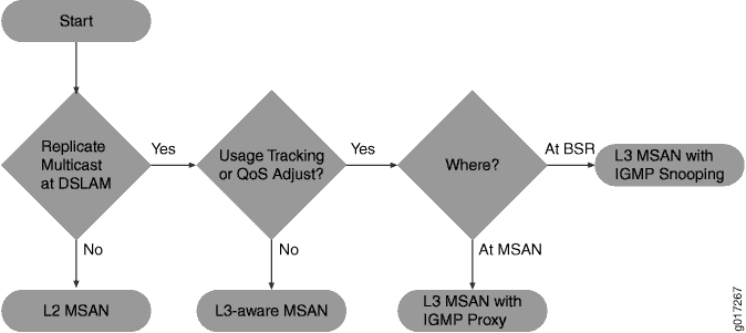
You can broadly categorize MSANs into three types based on how they forward traffic in the network:
  • Layer–2 MSAN—This type of MSAN is essentially a Layer 2 switch (though typically not a fully functioning switch) with some relevant enhancements. These MSANs use Ethernet (or ATM) switching to forward traffic. The MSAN forwards all subscriber traffic upstream to an edge router that acts as the centralized control point and prevents direct subscriber-to-subscriber communication. Ethernet Link Aggregation (LAG) provides the resiliency in this type of network.
    Layer 2 DSLAMs cannot interpret IGMP, so they cannot selectively replicate IPTV channels.
  • Layer–3 aware MSAN—This IP-aware MSAN can interpret and respond to IGMP requests by locally replicating a multicast stream and forwarding the stream to any subscriber requesting it. Layer 3 awareness is important when supporting IPTV traffic to perform channel changes (sometimes referred to as channel zaps). Static IP-aware MSANs always receive all multicast television channels. They do not have the ability to request that specific channels be forwarded to the DSLAM. Dynamic IP-aware DSLAMs, however, can inform the network to begin (or discontinue) sending individual channels to the DSLAM. Configuring IGMP proxy or IGMP snooping on the DSLAM accomplishes this function.
  • Layer–3 MSAN—These MSANs use IP routing functionality rather than Layer 2 technologies to forward traffic. The advantage of this forwarding method is the ability to support multiple upstream links going to different upstream routers and improving network resiliency. However, to accomplish this level of resiliency, you must assign a separate IP subnetwork to each MSAN, adding a level of complexity that can be more difficult to maintain or manage.

    Figure 1: Choosing an MSAN Type
     Choosing an MSAN Type


Share:

الخميس، 21 فبراير 2019

Commissioning RBS 6000 2G RUS (Step by step)

http://www.mediafire.com/file/t6w0triktnu9uyb/Commisioning+RBS+6000+2G.xls

http://www.mediafire.com/file/aa84tqaxr6y7zi0/RBS6000+GSM+Commissioning+Guide.pdf

http://www.mediafire.com/file/qtxk9pg5k8j4pp4/Serial+Cable+pin-out+for+RBS+6000+DUG.pptx

Step by step commissioning RBS 6000 2G RUS


Tools 


1) Laptop


2)  USB-serial cable + driver 


3) Serial DB9-RJ45 cable


DB9
RJ45


2

3


3

2


5

1


4) Software OMT


Step by step for Commisioning RBS 6000 2G


1. Create IDB (Installation Database)


> Click menu Configuration-->Create IDB


Cabinet Setup


> Click "New"


> Select RBS cabinet type


> Select Power System


> Select in Climate System


Antenna Sector Setup


> Click "New"


> define number of sector


> Select  Frequency Band, GSM 900 (B0/B8) or GSM 1800 (B3)


> Select Rx Diversity (2-Way / 4-way)


> Select Antenna Sharing


> definenumber of RUS, adjust with number of RUS actual


>  definewhat RBS use TMA or NOT


> Click "RE Setup"


> Select Tipe RUS (RUS01/RUS02)


> Select Radio Mode (Single/Mixed)


> definenumber of TRx per sector


2.
Change the view to "Cabinet 0", set the position of the modules in the RBS


> Click menu "Configuration-->define-->RU Position


> Determine the position of the shelf (shelf) and slot of each module


3. Define which modules we use in RBS (make sure the module we need is blue color, not lines)


> Click menu "Configuration-->define-->present RU


> Move the  modules that we need from the position of "not present" to "present" 


4. Define maximum power RRUS


> Click menu "configuration-->define-->MCTR"


> Contact INOC for setting


5. Define Node parameter --> Depend on configuration (see the sheet MSSM)


6. Setup transmision configuration


> Click menu "configuration-->define-->transmission"


> Select STN equipment


> Select Network Topology : (Stand alone / cascade)


7. Define gps parameter (if the configuration are Mixed mode or Dual DUG (using GPS cable))


> Click menu "configuration-->define-->Gps parameters 


> select GPS present " Yes"


8. Define Feeder and ESB Delay + TF Conpensation (if  the configuration is Antenna Sharing (using ESB cable) or MBC)


> Click menu "configuration-->define-->Feeder and ESB Delay


Define Feeder and ESB Delay


> Double click on ESB --> Add--> input data on  "delay(ns)" 


> Click menu "configuration-->define--> TF Compensation


    Define TF Compensation

> choose RBS GSM on Master RBS, input 17784 on master Transmitter chain delay, and input delay on ESB delay --> click appy


9. Define RBS Identity (optional)


> Click menu "configuration -->define--rbs identity


> Fill in RBS name and RBS description


11. Setup External alarm


> Click menu "configuration-->define-->alarm inlets"


> Select Hardware Unit = SAU


> Setup each alarm inlet


> inlet usage = external alarm


> type = closing (NO) / breaking (NC)


> ID


> Severity (level 1=critical, level 2=major)


> Comment = alarm name


12. Connect to RBS dan install IDB


> Click menu "RBS GSM-->Connect"


> Click menu "Configuration-->install IDB"


> Wait until finish


Note : When Install IDB (Configuration --> Install IDB)


make sure state of RBS is "Full Maintenance Mode" (Blue led lit steady)


How to change RBS:


> Select The view "system"


> Right click on GSM Node, and Select "Change Maintenance Mode"


> make sure Blue led lit steady


Share:

الأربعاء، 20 فبراير 2019

الاثنين، 18 فبراير 2019

Nokia PDFs for Commisioning , Antennas and SW upgrads

the below points will help you to learn some points in Nokia equipments

-Some information about SRAN:


http://www.mediafire.com/file/9a7uzyioyp424m9/TS-BTS-SW-0191-IP1.7_SRAN17A_1.3_P8.pdf/file

-illustrate types of antennas used with nokia equipments and how to connect and configure RET cable through FRGX :


http://www.mediafire.com/file/e36lazbh94pd2p3/OCI+Antenna+and+RET+deployments.pptx

 http://www.mediafire.com/file/wz3vd9lr6xfzvrm/Commissioning+RET.pdf


 SW upgrade and commissioning FSMF


http://www.mediafire.com/file/sid5cn3khm3brb4/TE+Nokia+Site+SW+Update+%26+Commission.pptx 

 
Share:
Hosam Hassan. يتم التشغيل بواسطة Blogger.